
Empty header
Warning: file_put_contents(): Only 0 of 728 bytes written, possibly out of free disk space in /var/www/clients/client9/web28/web/libraries/joomla/filesystem/file.php on line 435
_48.png)
Notice: Undefined offset: 77 in /var/www/clients/client9/web28/web/libraries/joomla/access/access.php on line 595
Notice: Trying to get property of non-object in /var/www/clients/client9/web28/web/libraries/joomla/access/access.php on line 595
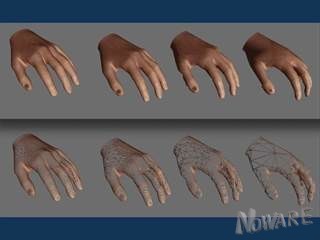
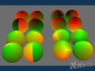
Shading is about defining an illumination model of the surface. The advanced notion is called BRDF for Bidirectional Reflectance Distribution Function. In general, it has 4 degrees of freedom, but it goes down to 3 for isotropic surfaces. First, we will show the impact of the roughness for both the diffuse and specular components. Using colors, the images are talkative enough, so I won't need a lot of text. When the surface has a roughness (micro-bumps), the diffuse reflection should change accordingly:
// Image
Such a diffuse reflection is way more complex than the typical "lambertian" model which is (wrongly) used everywhere. In the picture, it corresponds to the far-most row when the roughness is zero (for the diffuse, the roughness is called "diffusion", shown in red). When the diffusion increases, we get something closer to the shading of the moon, for example. But at the same time, another phenomenon must be taken into account: self-shadowing (shown in green). To get a physically accurate shading, one has to tune the proper level of self-shadowing compatible with the roughness/diffusion.
_________________________
The impact for the specular is also major. Most software only consider the highlight size (or light area) corresponding to the power N of the Blinn or Phong models. But the most important parameter is the roughness which is often neglected. Here is the effect in the specular reflection with the roughness in red and the light area in green:
// image
When the roughness is low, the light is concentrated, and when the roughness increases (along the red arrow), the same amount of light is distributed over a larger surface, decreasing the highlight intensity. Finally, combining the diffuse and specular components also needs a little bit of tuning to make the diffusion compatible with the roughness as they correspond to the same physical phenomenon.
 ;
;
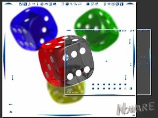
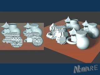
The little trick for metal shading is very simple. The parameter the user has access to is the "light area", sometimes it is wrongly called "roughness", but the right name is: "highlight size". What about the "roughness" then? Well the roughness is the surface roughness, and has nothing to do with the light size obviously.
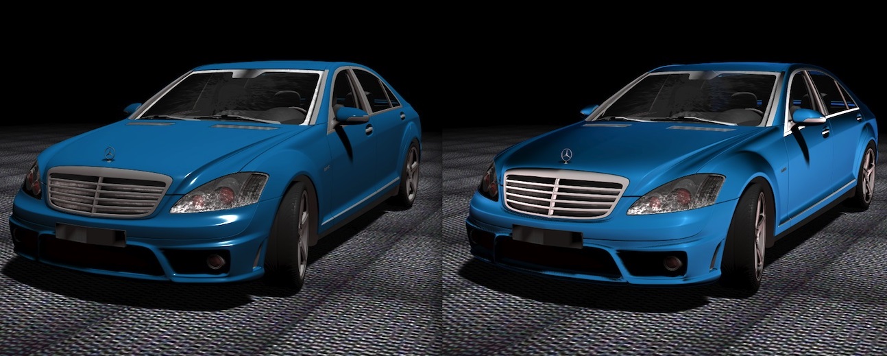
For the example, I use an object that is more likely to be metallic. It helps to see the point. On the top left (image "A") is the plastic version of the sport car. However, if we talk about metal, then only the specular is important. It gives the image "B", on the top right. It looks like metal, no problem, and you can do it. The problem is that most of the car gets black.
If we want the illumination to spread over more of the surface, we either increase the highlight size (you can do it), OR increase the roughness of the surface (you cannot do it). Changing the highlight gives the image "C" (bottom left), and changing the roughness instead gives the image "D" (bottom right). They are different. Since the light is still small for the image "D", there is a small highlight, but the car is not almost completely black. It shows the roughness in action.
This is trick #1: play with the roughness, not the highlight size.
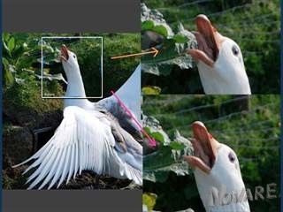
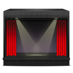
Now trick #2?... Don't use a uniform roughness. Even though the roughness of the metallic surface is perfectly uniform "in 3D", from a given angle, it is not uniform. The roughness is always view-dependent.
Simply put, if one sees the surface from a grazing angle, the roughness will surely decrease to zero, where the rough surface looks like a perfect mirror. Here is the result. A close-up shows the difference on a detail to better appreciate the effect.


_32.png)
_32.png)